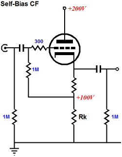

Worth breadboarding it, hopefully shortly.Ī typical challenge we may all face is how to drive effectively our amp via a stepped attenuator or an AVC. I think this could be a fantastic follower to use in multiple designs. PSR is about 60 to 70dB across the audio band so great addition to have a top active device here! I found that 100nF was enough to halve the distortion down to 0.0035% at 2Vrms! This minimises the distortion of the valve. C4 provides the bootstrapping between cathode and anode to force constant voltage operation at all times. The higher these are in value the smaller C4 is. M1 is the top follower which provides a fixed DC voltage using the resistor divider formed by R7 and R8. We can keep one single supply rail here but we need to elevate HT up to 180V minimum to provide the headroom required by the FET to operate well and minimise its output capacitances to ensure HF response is good. The stage gets a tad more complex, albeit not much. You can use the MOSFET of your choice here: But to avoid elevating heating, I just went for a straight sanded follower using a depletion FET, the famous DN2540. The “extra follower” on top of the cathode follower could be another valve. Thanks to Tim’s suggestion to implement Allen Wright’s Super Linear Cathode Follower (SLCF) which forces the valve to operate in constant voltage (in addition to the constant current) by bootstrapping the cathode to the anode using an extra follower, distortion is reduced further.

High-value resistors are available on 1% but the variance on the FET defeat the purpose of accurately building the resistor divider.Ĭontinue reading “Testing the line stage” The clear challenge of the SLCF is establishing the correct bias point on the top follower due to the high value of the resistor divider and the high-variance we typically get on the VGS(th) of the MOSFETs. I didn’t, thanks to the ferrite beads and stoppers. 200MHz) you can spot out any nasty oscillation from the valve. If you pay attention to this and check with an oscilloscope with sufficient bandwidth (e.g. Also some grid/screen stopper resistors (e.g. So we then are a bit more precocious when building the test jig and “try” to have short connections (something which I didn’t do), add some ferrite beads to anode, grid and screen. One of the challenges we face when building a cathode follower with a high-gain / transconductance valve is that it can easily oscillate widely into VHF. The usual challenges we face when breadboarding circuits Wiring it then point-to-point could be done in a matter of minutes and a “rat nest” was built fast enough to enjoy this learning experience. It was question of building a simple PCB for the tail CCS and the top MOSFET follower.
CATHODE FOLLOWER UPDATE
The results update as new input values are entered ~ Values for g m r a and µ should be taken from the valve characteristics or manufacturers data ~ The default values are for an ECC81 with V 1 Ia ≈1mA and Cathode follower V 2 Ia ≈2.I couldn’t resist the temptation to try and build quickly the SLCF design proposed here.

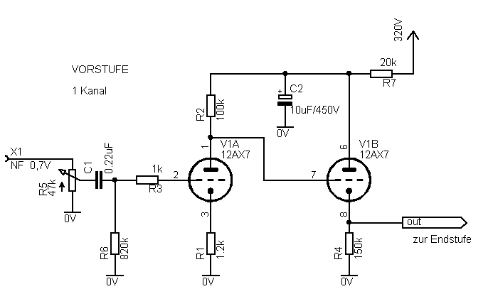
This Calculator is to support my Amplifier≫uffer project and can be used to calculate the gain of a triode amplifier using a common cathode gain stage with a cathode follower output buffer so the overall gain is not significantly affected by the output load The following calculator will not function Which your browser does not appear to have enabled


 0 kommentar(er)
